整理完
Blynk 控制器元件後, 繼續來看看顯示元件 (Displays). 顯示元件主要用來呈現從硬體設備端取得的資料並加以圖形化, 對 App 而言是從遠端設備讀取數據 (Read), 這可以用兩種方式達成, 一個方式是由 Blink App 的顯示元件主動向硬體設備發出週期性的要求 (Request); 另一個方式是由硬體設備向 Blink App 顯示元件定期推送資料 (Push).
目前有十種顯示元件如下 :
其中 Graph (曲線圖或長條圖) 與 Gauge (儀表) 我已經在上週利用 Blynk 顯示 Arduino 溫溼度與照度對 Blynk 初步測試時使用過了, 參考 :
#
Blynk 應用 (二) : 在手機顯示即時溫溼度與光度
以下測試程式是在我自己用洞洞板焊接的 Arduino Nano+ESP8266 IOT 模組上進行實驗, 電路圖參考 :
#
製作 Arduino Nano + ESP8266 物聯網模組 (四) : 完結篇
若懶得焊接板子, 可以照上面電路圖自行用麵包板接線, 只不過 AMS1117 不是 DIP 封裝, 沒辦法插入麵包板, 比較麻煩而已.
一. 數值顯示器 (Value Display) :
此種顯示元件有四個, 可以綁定硬體設備的 Digital/Analog/Virtual 輸出腳, 主要差別是元件外觀的大小與是否具有將輸出資料格式化的功能 :
- Value Display S : 數值顯示器 (短)
- Value Display M : 數值顯示器 (中)
- Labeled Value M : 格式化的數值顯示器 (中)
- Labeled Value L : 格式化的數值顯示器 (長)
前兩種的設定畫面如下 :
"VALUE" 框填入此顯示器標題, 例如溫度, 溼度等. PIN 可以選 Digital/Analog/Virtual, 右邊是其數值上下限值. 而 Reading Frequncy 為讀取頻率, 預設 1 秒, 這表示 Blynk App 會週期性向硬體設備發出讀取要求, 如果此顯示器綁定的是實體腳位 (Digital/Analog), 則設備端不需要寫傳送資料的程式碼, Blynk App 會自動取得資料.
但是, 如果綁定虛擬腳位 (Virtual Pin), 則設備端韌體程式必須將資料寫入該虛擬腳位, App 才會收到所傳遞的數據. 以 Arduino 來說, 必須定義一個 BLYNK_READ(vPin) 函數, 然後呼叫 Blynk.virtualWrite() 將資料傳送給 App.
例如下面這個範例是顯示程式執行以來經過之秒數 :
#define BLYNK_PRINT Serial //Comment this out to disable prints and save space
#include <SoftwareSerial.h>
#include <ESP8266_Lib.h>
#include <BlynkSimpleShieldEsp8266.h>
SoftwareSerial esp8266(7, 8); //(RX, TX)
ESP8266 wifi(&esp8266); //create wifi object
char ssid[]="EDIMAX-tony";
char pass[]="1234567890";
char auth[]="e80fe6aae0d442518820f61xxxxxx8f5";
void setup() {
Serial.begin(9600); //Set console baud rate
esp8266.begin(9600); //Set ESP8266 baud rate
Blynk.begin(auth, wifi, ssid, pass);
}
void loop() {
Blynk.run();
}
BLYNK_READ(V0) {
Serial.println(millis()/1000);
Blynk.virtualWrite(
V0, millis()/1000);
}
使用虛擬腳位時, Reading Frequncy 也可以選擇 PUSH 模式, 從硬體設備推送資料到 Blynk App, 而非由 App 提出要求, 如下圖所示 :
這必須配合計時器 (Timer) 週期性地呼叫 Blynk.virtualWrite() 向 Blynk App 推送資料, 才能讓顯示器元件呈現即時數據, 例如 :
#define BLYNK_PRINT Serial //Comment this out to disable prints and save space
#include <SoftwareSerial.h>
#include <ESP8266_Lib.h>
#include <BlynkSimpleShieldEsp8266.h>
#include <SimpleTimer.h>
SoftwareSerial esp8266(7, 8); //(RX, TX)
ESP8266 wifi(&esp8266); //create wifi object
SimpleTimer timer; //create a Timer object
char ssid[]="EDIMAX-tony";
char pass[]="1234567890";
char auth[]="e80fe6aae0d442518820f61xxxxxx8f5";
void setup() {
Serial.begin(9600); //Set console baud rate
esp8266.begin(9600); //Set ESP8266 baud rate
Blynk.begin(auth, wifi, ssid, pass);
timer.setInterval(1000L,
pushUptime); //Don't send more that 10 values per second
}
void loop() {
Blynk.run();
timer.run();
}
void pushUptime() { //push Arduino uptime to virtual pin V0
Serial.println(millis()/1000);
Blynk.virtualWrite(V0, millis()/1000);
}
在上面的程式中, 為了使用計時器, 我們匯入了 SimpleTimer 函式庫並建立了 SimpleTimer 物件, 在 setup() 函式中呼叫計時器物件的 setInterval() 方法並指定每秒觸發 pushUptime() 函式一次, 呼叫 Blynk.virtualWrite() 將程式執行以來所經過的秒數寫入虛擬腳位 V0, 這樣 App 上就會即時顯示程式執行已過了幾秒了 :
注意, 千萬不可以把 Blynk.VirtualWrite() 放在 loop() 迴圈函數中, 這樣會傳送太頻繁的資料給 Blynk Cloud 伺服器, 造成所謂 "Flood Error", 參考 :
#
http://docs.blynk.cc/#troubleshooting-flood-error
務必如上例所示使用 SimpleTimer 計時器函數來控制數據傳輸頻率. 當資料傳送頻率超過每秒 20 筆時, Blynk Cloud 會自切斷連線, 手機 Blynk App 會顯示 "Your hardware is offline".
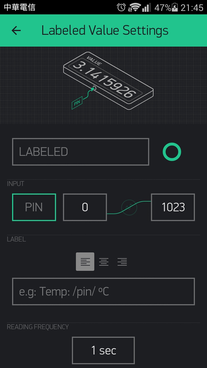
接下來看看格式化的顯示器元件, 此元件提供四種格式化字串, 可設備端傳來的數據機以期望的格式顯示 :
| 格式 | 作用 (原始數據例如 12.6789) |
| /pin/ | 不格式化, 顯示原始數據 12.6789 |
| /pin./ | 顯示四捨五入後之整數部分 13 |
| /pin.#/ | 顯示四捨五入後至小數後一位 12.7 |
| /pin.##/ | 顯示四捨五入後至小數後兩位 12.68 |
其設定畫面與 Value Display 相同, 只是多了一個 LABEL 欄位而已, 可將上面的格式化字串插入任何字串, 例如 "溫度 /pin.##/ 度" 就會顯示至小數後兩位 :
下面範例是從 DHT11 取得溫濕度後, 利用 PUSH 方式推送至格式化數值顯示器, 但不格式化而是顯示原始數據, 溫度使用虛擬腳位 V0, 濕度使用虛擬腳位 V1, 手機 App 設定如下 :
設備端程式如下 :
#define BLYNK_PRINT Serial //Comment this out to disable prints and save space
#include <SoftwareSerial.h>
#include <ESP8266_Lib.h>
#include <BlynkSimpleShieldEsp8266.h>
#include <SimpleTimer.h>
#include "DHT.h"
#define DHTPIN 6
#define DHTTYPE DHT11
SoftwareSerial esp8266(7, 8); //(RX, TX)
ESP8266 wifi(&esp8266); //create wifi object
SimpleTimer timer; //create a Timer object
DHT dht(DHTPIN, DHTTYPE); // Initialize DHT sensor
char ssid[]="EDIMAX-tony";
char pass[]="1234567890";
char auth[]="e80fe6aae0d442518820f61xxxxxx8f5";
void setup() {
Serial.begin(9600); //Set console baud rate
esp8266.begin(9600); //Set ESP8266 baud rate
Blynk.begin(auth, wifi, ssid, pass);
timer.setInterval(1000L, pushWeather); //Don't send more that 10 values per second
}
void loop() {
Blynk.run();
timer.run();
}
void pushWeather() { //push Arduino uptime to virtual pin V0
float Temperature=dht.readTemperature(); //get temperature (C) from DHT11
float Humidity=dht.readHumidity(); //get humidity from DHT11
Serial.print("Temperature=" + (String)Temperature + " ");
Serial.println("Humidity=" + (String)Humidity);
Blynk.virtualWrite(
V0, Temperature);
Blynk.virtualWrite(
V1, Humidity);
}
結果如下 :
由於 DHT11 精確度只到整數, 因此推送給 App 的原始數據小數部分是 .000 的浮點數. 可見格式化顯示元件的好處是可以隨意控制想要呈現的輸出格式, 除了收到的原始數據可格式化外, 還能添加其他文字. 此專案分享如下 :
二. LED 顯示器 :
此元件用來在手機上以燈光明亮度顯示遠端數據, 其值介於 0~255 之間, 0 會讓 LED 燈滅, 而 255 讓 LED 最亮. LED 只能綁定到虛擬腳位, 不能綁定 Digital 或 Analog 腳. 其設定畫面如下 :
在設備端的韌體程式裡, 必須先建立對應此虛擬腳位的 WidgetLED 物件, 呼叫此物件的 setValue() 方法可以設定 LED 的值 (0~255), 呼叫 on() 可將 LED 設為最亮, 相當於呼叫 setValue(255); 而呼叫 off() 方法則熄滅 LED, 相當於呼叫 setValue(0). 呼叫 getValue() 則可以取得目前 LED 的亮度值 (0~255).
下面範例是由設備端透過虛擬腳位 V0 控制 Blynk App 的 LED 燈每秒閃爍 :
#define BLYNK_PRINT Serial //Comment this out to disable prints and save space
#include <SoftwareSerial.h>
#include <ESP8266_Lib.h>
#include <BlynkSimpleShieldEsp8266.h>
#include <SimpleTimer.h>
SoftwareSerial esp8266(7, 8); //(RX, TX)
ESP8266 wifi(&esp8266); //create wifi object
SimpleTimer timer; //create a Timer object
WidgetLED led0(
V0);
char ssid[]="EDIMAX-tony";
char pass[]="1234567890";
char auth[]="e80fe6aae0d442518820f61xxxxxxx8f5";
void setup() {
Serial.begin(9600); //Set console baud rate
esp8266.begin(9600); //Set ESP8266 baud rate
Blynk.begin(auth, wifi, ssid, pass);
timer.setInterval(1000L, blinkLED); //Don't send more that 10 values per second
}
void loop() {
Blynk.run();
timer.run();
}
void blinkLED() { //push Arduino uptime to virtual pin V0
if (led0.
getValue()) { //LED not off
led0.
off();
Serial.println("LED V0: off");
}
else { //LED off
led0.
on();
Serial.println("LED V0: on");
}
}
執行結果 LED 燈確實會每秒閃爍一次 :
下面範例則是使用 setValue() 讓 LED 越來越亮, 到達 255 後又越來越暗, 如此周而復始 :
#define BLYNK_PRINT Serial //Comment this out to disable prints and save space
#include <SoftwareSerial.h>
#include <ESP8266_Lib.h>
#include <BlynkSimpleShieldEsp8266.h>
#include <SimpleTimer.h>
SoftwareSerial esp8266(7, 8); //(RX, TX)
ESP8266 wifi(&esp8266); //create wifi object
SimpleTimer timer; //create a Timer object
WidgetLED led0(V0);
int i;
boolean brighter=true;
char ssid[]="EDIMAX-tony";
char pass[]="1234567890";
char auth[]="e80fe6aae0d442518820f61xxxxxx8f5";
void setup() {
Serial.begin(9600); //Set console baud rate
esp8266.begin(9600); //Set ESP8266 baud rate
Blynk.begin(auth, wifi, ssid, pass);
timer.setInterval(1000L, brighter_darker_toggle); //Don't send more that 10 values per second
}
void loop() {
Blynk.run();
timer.run();
}
void brighter_darker_toggle() { //push Arduino uptime to virtual pin V0
if (brighter) {
if (i < 255) {i += 5;} //brighter
else {brighter=false;} //darker
}
else { //darker
if (i > 0) {i -= 5;} //darker
else {brighter=true;} //brighter
}
Serial.println(i);
led0.
setValue(i);
Blynk.
virtualWrite(V1, i);
}
在此範例中, 我另外添加了一個 Value Display 來顯示亮度值, 並將其綁定到虛擬腳位 V1 :
三. LCD 液晶顯示器 :
此元件模擬 1602 液晶顯示器, 其設定畫面如下 :
它有 Simple 與 Advanced 兩種模式可選, 所謂的 Advanced 模式是把 LCD 顯示元件當成真正的 1602 一樣, 必須先建立一個 WidgetLCD 物件, 然後呼叫 print() 函數輸出到手機 App 上指定的虛擬腳位 (
Advanced 模式只能使用 Virtual Pin), 下列範例是在 LCD 上顯示 "Hello World", 綁定到 App 的虛擬腳位 V0, 設定如下 :
Colors 欄位可設定 LCD 背景與文字顏色.
程式如下 :
#define BLYNK_PRINT Serial //Comment this out to disable prints and save space
#include <SoftwareSerial.h>
#include <ESP8266_Lib.h>
#include <BlynkSimpleShieldEsp8266.h>
SoftwareSerial esp8266(7, 8); //(RX, TX)
ESP8266 wifi(&esp8266); //create wifi object
WidgetLCD lcd(
V0);
char ssid[]="EDIMAX-tony";
char pass[]="1234567890";
char auth[]="e80fe6aae0d442518820f61xxxxxx8f5";
void setup() {
Serial.begin(9600); //Set console baud rate
esp8266.begin(9600); //Set ESP8266 baud rate
Blynk.begin(auth, wifi, ssid, pass);
while (Blynk.connect() == false) {} //wait until connected
lcd.
clear(); //clear LCD screen
lcd.
print(4, 0, "Hello"); //(X: 0-15, Y: 0-1, "message")
lcd.
print(4, 1, "World"); //(X: 0-15, Y: 0-1, "message")
}
void loop() {
Blynk.run();
}
上面程式中, 輸出到 LCD 的 print() 是放在 setup() 裡, 這樣設備開機後 LCD 螢幕顯示完 Hello World 便不動了. 如果要顯示變動資料, 同樣地, 為了避免要求太頻繁造成 Flood Error, 不可以把 print() 指令直接放在 loop 裡, 而是要將其放在一個函數中, 利用 SimpleTimer 物件的 setInterval() 去設定週期性觸發此函數.
例如下面的範例是將上面的程式已執行時間改在 LCD 元件顯示 :
#define BLYNK_PRINT Serial //Comment this out to disable prints and save space
#include <SoftwareSerial.h>
#include <BlynkSimpleShieldEsp8266.h>
#include <
SimpleTimer.h>
SoftwareSerial esp8266(7, 8); //(RX, TX)
ESP8266 wifi(&esp8266); //create wifi object
SimpleTimer timer; //create a Timer object
WidgetLCD lcd(V0);
char ssid[]="EDIMAX-tony";
char pass[]="1234567890";
char auth[]="e80fe6aae0d442518820f61xxxxxx8f5";
void setup() {
Serial.begin(9600); //Set console baud rate
esp8266.begin(9600); //Set ESP8266 baud rate
Blynk.begin(auth, wifi, ssid, pass);
lcd.clear(); //clear LCD screen
timer.
setInterval(1000L,
pushUptime); //Don't send more that 10 values per second
}
void loop() {
Blynk.run();
timer.run();
}
void
pushUptime() { //push Arduino uptime to virtual pin V0
lcd.print(0, 0, "Uptime"); //(X: 0-15, Y: 0-1, "message")
lcd.print(0, 1, millis()/1000); //(X: 0-15, Y: 0-1, "message")
}
回到 Simple mode, 此模式將 1602 的兩排文字當成是腳位, 可以綁定到 Analog 與 Virtual 兩種腳位, 這樣就與上面的 Value Display 類似, 可以選擇 Reading 或 Push 模式來取得設備端的資料, Push 模式是在設備端韌體程式中, 使用計時器自行將資料推送到 App 中, 必須用 Blynk.VirtualWrite() 將資料輸出到虛擬腳位 (因此只能綁定虛擬腳位); 而 Reading 模式則是在 Blynk App 中的 Reading Frequency 欄位中指定固定周期向設備端要求資料, 可以綁定 Analog 或 Virtual 腳位, 若綁定虛擬腳位, 則設備端韌體程式必須準備 BLYNK_READ(vPin) 函式才行, 若綁定 Analog 腳位就不用.
下面範例程式是使用 Push 模式向 App 的 V0 推送程式執行以來的秒數, 向 V1 推送毫秒數 :
程式如下 :
#define BLYNK_PRINT Serial //Comment this out to disable prints and save space
#include <SoftwareSerial.h>
#include <BlynkSimpleShieldEsp8266.h>
#include <
SimpleTimer.h>
SoftwareSerial esp8266(7, 8); //(RX, TX)
ESP8266 wifi(&esp8266); //create wifi object
SimpleTimer timer; //create a Timer object
char ssid[]="EDIMAX-tony";
char pass[]="1234567890";
char auth[]="e80fe6aae0d442518820f61xxxxxx8f5";
void setup() {
Serial.begin(9600); //Set console baud rate
esp8266.begin(9600); //Set ESP8266 baud rate
Blynk.begin(auth, wifi, ssid, pass);
timer.
setInterval(1000L,
sendSeconds); //Don't send more that 10 values per second
timer.
setInterval(1000L,
sendMillis); //Don't send more that 10 values per second
}
void loop() {
Blynk.run();
timer.
run();
}
void
sendSeconds() {
Blynk.virtualWrite(
V0, millis() / 1000);
}
void
sendMillis() {
Blynk.virtualWrite(
V1, millis());
}
如果採用 Reading 模式的話, 設備端韌體程式就不需要費心使用計時器推送了 (不需要匯入 SimpleTimer 函式庫), 但若綁定虛擬腳位, 必須準備 BLYNK_READ() 函數對應, 設定如下 :
程式如下 :
#define BLYNK_PRINT Serial //Comment this out to disable prints and save space
#include <SoftwareSerial.h>
#include <BlynkSimpleShieldEsp8266.h>
SoftwareSerial esp8266(7, 8); //(RX, TX)
ESP8266 wifi(&esp8266); //create wifi object
char ssid[]="EDIMAX-tony";
char pass[]="1234567890";
char auth[]="e80fe6aae0d442518820f61xxxxxx8f5";
void setup() {
Serial.begin(9600); //Set console baud rate
esp8266.begin(9600); //Set ESP8266 baud rate
Blynk.begin(auth, wifi, ssid, pass);
}
void loop() {
Blynk.run();
}
BLYNK_READ(
V0) {
Blynk.virtualWrite(
V0, millis() / 1000);
}
BLYNK_READ(
V1) {
Blynk.virtualWrite(
V1, millis());
}
所以 Reading 模式在設備端韌體部分比較簡單, 但結果是一樣的. 注意, LCD 在 Simple mode 下兩列 message 都是可以格式化的, 用法跟上面 Formated Value Display 元件完全一樣.
四. 終端機元件 (Terminal) :
此元件除了用來顯示設備端訊息外, 也可以從 App 對設備下達指令, 模擬一般 Command Line 通訊軟體如 Putty 的基本雙向通訊功能. 此元件只能綁定虛擬腳位, 作為設備與 App 間的溝通介面, 其設定畫面如下 :
其中 INPUT LINE 欄位設定是否要開啟輸入框, 若設為 ON, 則終端機視窗底下會有一個輸入框, 使用者若輸入文字再按 Enter, 就會透過所綁定的虛擬腳位 (INPUT 選項) 傳送給設備, 這樣 BLYNK_WRITE(vPin) 函數就會被呼叫, 我們可在此函數中處理回應, 利用呼叫終端機物件的 println() 函數來將回應訊息傳給 App (當然是透過所綁定之虛擬腳位). 如果只是要像 LCD 那樣顯示設備端資訊, 不需要向設備下指令, 就可以設為 OFF. AUTOSCROLL 欄位設定輸出訊息是否要自動向下捲動.
設備端韌體程式必須建立一個 WidgetTermal 物件, 它類似序列埠物件, 透過呼叫 print(), println(), write() 以及 flush() 等函數向虛擬腳位輸出訊息, 傳送到 App 的 Terminal 元件上. 終端機回應處理部分使用的是 Reading (Request) 模式, 亦即必須為虛擬腳位準備 BLYNK_WRITE() 函數來處理回應訊息.
下面範例改寫自官網說明文件 :
#define BLYNK_PRINT Serial //Comment this out to disable prints and save space
#include <SoftwareSerial.h>
#include <ESP8266_Lib.h>
#include <BlynkSimpleShieldEsp8266.h>
SoftwareSerial esp8266(7, 8); //(RX, TX)
ESP8266 wifi(&esp8266); //create wifi object
WidgetTerminal terminal(
V0);
char ssid[]="EDIMAX-tony";
char pass[]="1234567890";
char auth[]="e80fe6aae0d442518820f61xxxxxx8f5";
void setup() {
Serial.begin(9600); //Set console baud rate
esp8266.begin(9600); //Set ESP8266 baud rate
Blynk.begin(auth, wifi, ssid, pass);
while (Blynk.connect() == false) {} //wait until connected
terminal.
println(F(
"Blynk v" BLYNK_VERSION ": Device started"));
terminal.println(F("-------------"));
terminal.println(F("Type 'Hello' and get a reply, or type"));
terminal.println(F("anything else and get it printed back."));
terminal.
flush(); //Ensure everything is sent
}
void loop() {
Blynk.run();
}
BLYNK_WRITE(
V0) { //called when V0 updated (user send data to V0)
if (String("Hello") ==
param.asStr()) { //if receives "Hello"
terminal.
println(F("You said: 'Hello'")); //show user command "Hello" in Widget
terminal.
println(F("I said: 'World'")); //show hardware response "World"
}
else { //otherwise send it back
terminal.
print(F("You said:"));
terminal.
write(param.
getBuffer(), param.
getLength()); //echo
terminal.
println(); //new line
}
terminal.
flush(); //Ensure everything is sent
}
此程式的 BLYNK_WRITE() 函數就是處理 App 端虛擬腳位 V0 傳來的 Reading Request, 其要求參數 param 攜帶了使用者在 Terminal 元件所下指令, 經字串比對若指令為 "Hello", 就回應 "World", 否則就將指令 echo 回去, 這時會呼叫 getBuffer() 函數取得緩衝器內的 raw data, 再用 write() 函數寫回去. 結果如下 :
這很像 Linux 的 shell 對吧! 注意, 上面的程式中使用了 Blynk 函式庫定義的版本常數 BLYNK_VERSION, 放在 F() 函數內直接與常數字串相接即可, 不可用 "+" 串接.
五. 歷史圖形元件 (History Graph) :
之前曾經使用 Graph 元件來顯示氣候資料, 可以顯示量測值隨時間變化的圖形 (折線圖或長條圖), 參考 :
#
Blynk 應用 (二) : 在手機顯示即時溫溼度與光度
然而 Graph 元件的時間尺度是固定無法調整的, 沒辦法看到之前的數據變化情形. 而此 History Graph 元件提供三種格局的尺度, 可以讓我們放大縮小時間軸, 以便觀察之前傳送到 Blynk 雲端伺服器的資料. 此元件可以綁定 Digital/Analog/Virtual 三種腳位, 但一個元件只能同時觀察四個量測變數, 設定畫面如下 :
History Graph 是顯示過去曾傳送到伺服器的所有資料, 因為我之前使用 V0, V1, V2 做過別的實驗, 這裡為了演示, 避免之前的數據讓圖形很奇怪 (例如 V0 之前用來傳送程式執行秒數, 其數值高達數萬, 現在拿來顯示溫度又變成 20~30, 其歷史圖形就很突兀), 所以我改用 V4~V7 當參數. 雖然目前我手邊沒有氣壓計模組, 我還是補上去, 免得四個通道有一個是空的. 底下 "Show Legend" 欄位預設 OFF, 設為 ON 會在上方顯示四個參數的圖例 (曲線顏色說明).
注意, 上面設定項目裡面沒有 Reading Frequency 可選, 這是因為此元件是用來從雲端資料庫中取出所指定之腳位了歷史資料來顯示, 所以並不需要為此元件特別定義資料驅動方式, 這些腳位由其他程式碼驅動, History Graph 只是從資料庫取出歷史資料來顯示而已. 在下面程式碼中為了演示之故, History Graph 元件特別使用 Push 方式以計時器推送資料給 V4~V7, 正常應用情況下可能是用其他顯示元件如 Gauge 以 Reading 模式取得資料. 程式如下 :
#define BLYNK_PRINT Serial //Comment this out to disable prints and save space
#include <SoftwareSerial.h>
#include <BlynkSimpleShieldEsp8266.h>
#include <
SimpleTimer.h>
#include "DHT.h"
#define DHTPIN 6
#define DHTTYPE DHT11
SoftwareSerial esp8266(7, 8); //(RX, TX)
ESP8266 wifi(&esp8266); //create wifi object
SimpleTimer timer; //create a Timer object
DHT dht(DHTPIN, DHTTYPE); //Initialize DHT sensor
char ssid[]="EDIMAX-tony";
char pass[]="1234567890";
char auth[]="e80fe6aae0d442518820f61xxxxxx8f5";
void setup() {
Serial.begin(9600); //Set console baud rate
esp8266.begin(9600); //Set ESP8266 baud rate
Blynk.begin(auth, wifi, ssid, pass);
while (Blynk.connect() == false) {} //wait until connected
timer.
setInterval(1000L, pushWeather); //Don't send more that 10 values per second
}
void loop() {
Blynk.
run();
timer.
run();
}
void pushWeather() {
float Temperature=dht.readTemperature(); //get temperature (C) from DHT11
float Humidity=dht.readHumidity(); //get humidity from DHT11
int cds=analogRead(A0); //get cds voltage (0~5V to 0~1023 dark)
int Luminance=100-map(cds,0,1023,0,100); //map 0~1023(dark) to 0(dark)~100%
Blynk.
virtualWrite(
V4, Temperature);
Blynk.
virtualWrite(
V5, Humidity);
Blynk.
virtualWrite(
V6, Luminance);
}
這裡利用計時器每秒將氣候資料透過虛擬腳位推送到雲端, 然後顯示在手機 App 上. 下面是一小時尺規內 (1h) 的歷史圖形 :
可見此元件提供六種時間尺規來顯示圖形 :
- 1h : 一小時
- 6h : 六小時
- 1d : 一天
- 1w : 一周
- 1m : 一個月
- 3m : 三個月
亦即, History Graph 最長也只能顯示過去 3 個月的歷史圖形. 點 6h 即切換到六小時尺規內的歷史圖形如下 :
在 Play 狀態下, 於歷史圖形上向左邊滑動, 會出現如下畫面 :
按 "Export to CSV" 會將此元件所綁定腳位的歷史資料以 CSV 壓縮檔寄送到郵件信箱 :
因上面程式實際上只有 V4~V6 三支虛擬腳位有資料, 所以只有三個壓縮檔 :
解壓縮後的 CSV 檔內容如下 (此為溫度 V4) :
按下面的 "Erase Data" 則會刪除此元件所綁定的所有腳位之歷史資料.
刪除後資料庫便無資料, 顯示 "No data" :
OK, 以上便是顯示元件的用法測試.
參考 :
#
Blynk HTTP RESTful API